Resistance in series and parallel circuits
Combinations of resistance in electric circuit
There are two possible combinations of resistance in electric circuits:
-
Series combination
-
Parallel combination
-
Series combination
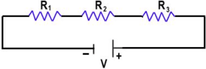
In series combinations, resistors are connected end to end and electric current has a single path through the circuit. This means that the current passing through each resistor is the same.

The current is the same through all points in the series circuit. The current through each resistor in a series circuit is the same as the current through all the resistors that are in series with it. In the above figure, three resistors are connected in series to a DC voltage source. At any point in this circuit, the current into that point must equal the current out of that point. Notice also that the current out of each resistor must equal the current into each resistor because there is no place where part of the current can branch off and go somewhere else. Therefore, the current in each section of the circuit is the same as the current in all other sections. It has only one path going from the positive(+) side of the source to the negative (_) side.
See also: Emf Vs p.D
Total series resistance
The total series resistance of a series circuit is equal to the sum of the resistance of each individual series resistor. When resistors are connected in series, the resistor values add because each resistor offers opposition to the current in the direct proportion to its resistance. A greater number of resistors connected in series creates more opposition to current. More opposition to current implies a higher value of resistance. Thus, every time a resistor is added in series, the total resistance increases.
total resistance in series circuit
For any number of individual resistors connected in series, the total resistance is the sum of each of the individual values.
Rt=R1+R2+R3+R4+………..+Rn
Where Rt is the total resistance and Rn is the last resistor in the series string. For example, if there are 3 resistors in series .the total resistance formula will be
Rt=R1+R2+R3
If there are six resistors in series (n=6), the total resistance formula will be:
Rt=R1+R2+R3+R4+R5+R6
2:Parallel combination
When two or more resistors are individually connected between the same two separate points, they are in parallel with each other. A parallel circuit provides more than one path for current.
Each current path is called a branch. A parallel circuit is one more that has more than one branch. Three resistors are connected in parallel shown in the above figure. When resistors are connected in parallel, the current has more than one path. The number of current paths is equal to the number of parallel branches.
Total resistance in parallel circuit
Since Vs is the voltage across each of the parallel resistors in the above figure, by Ohm’s law I=Vs/R:
Vs/Rt= Vs/R1+ Vs/R2+ Vs/R3…….(1)
The term Vs can be factored out of the right side of the equation and canceled with Vs on the left side, leaving only the resistance terms.
1/Rt = 1/R1 + 1/R2 + 1/R3……(2)
Recall that the reciprocal of resistance (1/R) is called conductance, which is symbolized by G.The unit of conductance is the Siemens (s). Equation (2) can be expressed in terms of conductance as:
Gt = G1 + G2 + G2
Solve for Rt in equation (2) by taking the reciprocal of that is inverting both sides of the equation.
Rt= 1/ (1/R1) + (1/R2)+ (1/R3)
Related Topics:
Recent Posts
Is energy quantized in classical physics?
No, according to classical wave theory the emission of electromagnetic radiations from the surface is…
Types of laser
Basically, there are four types of laser which includes: Gas Lasers Solid State lasers Liquid…
Ultrasound frequency range
What is ultrasonics? The study and application of mechanical vibrations with frequencies beyond the limits…
Electromagnetic Energy: What are some examples of it?
Electromagnetic energy definition Electromagnetic energy is the amount of energy stored in a region of…
Fundamental units and Derived Units with Examples
The Main Difference between fundamental Units and Base units is that Units that Express base…
Newton’s First law of Motion Examples in Our Daily Life
Newton's first law of motion states that " A body continues its state of rest…
View Comments
What is Gt ? ______________________________________________
What is Vs ? ______________________________________________
What is Rn ? ______________________________________________