What are the applications of carnot cycle?
Carnot heat engine and refrigeration are one of the Carnot cycle applications.
Now!
We learn in detail about the Carnot cycle and the Carnot engine.
What is Carnot Engine?
Sadi Carnot in 1840 described an ideal engine using only isothermal and adiabatic processes. The Carnot engine is free from friction and heat loss. Sadi showed that a heat engine operating in an ideal reversible cycle between two heat reservoirs at different temperatures would be the most efficient.
Construction of Carnot engine:
It consists of following parts:
- A cylinder containing perfect gas having non conducting walls and piston and conducting base.
- A source of heat at temperature TH.
- A sink at temperature TL.
- A non conducting stand
Carnot cycle
The operating cycle of Carnot engine is called Carnot cycle.The Carnot cycle consist of following four process:
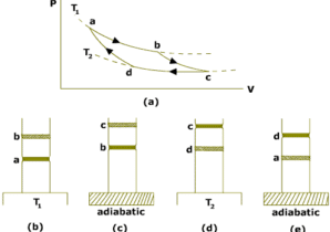
Isothermal expansion:
The cylinder is placed on the source of heat at temperature TH and gas is allowed to expand very slowly by removing weights on the piston.During this process,heat QH is absorbed by the gas from the source.Since in isothermal process,temperature of the system remains constant,so internal energy of the gas does not change Eint=0.All the heat added to the system appears as the work done on the gas.This process is shown on PV diagram by the curve AB.
Adiabatic Expansion:
The cylinder is now placed on the non-conducting stand so that heat does not enter or leave the gas. The gas is allowed to expand slowly by removing more weights from the piston.The process is adiabatic so Q=0.The piston does negative work on the gas and the work is done at the cost of the internal energy of the gas.So the temperature of the gas decreases to TL. This process is shown on the PV diagram by the curve BC.
Isothermal Compression:
The cylinder is now placed on the sink and the gas is compressed by adding weights on the piston. During this process the gas rejects heat QL to sink at TL. This process is shown in the PV diagram by the curve CD.
Adiabatic Compression:
The cylinder is finally placed on the non-conducting stand. The gas is compressed by adding more weights on the piston. Since the process is adiabatic,so no heat can enter or leave the system. Work is done on the gas due to which temperature of the gas increases to TH. Thus the gas returns back to initial state and the cycle is completed. The process is shown on the PV diagram by curve DA.
So the gas undergoes a cycle ABCDA. It is a reversible cycle and is called carnot cycle.
The four steps described above are illustrated in PV diagram shown in figure below.
Efficiency of carnot engine:
Let us now calculate the efficiency of a carnot engine.
Watch also video about carnot engine: