what is Difference between induced emf and induced current?
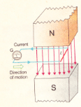
 There are many ways to produce induced emf figures illustrated one of them. Consider a straight piece of wire of length l placed in the magnetic field of a permanent magnet. The wire is connected to a sensitive galvanometer. This forms a closed path or loop without any battery. In the beginning, when the loop is at rest in the magnetic field, no current is shown by the galvanometer. If we move the loop from left to right, the length l of the wire is dragged across the magnetic field and a current follows through the loop. As stop moving the loop, the current also stops. Now, if we move the loop in the opposite direction, the current also reverses its direction. This is indicated by the deflection of the galvanometer opposite direction.
The induced current depends upon the speed with which the conductor moves and upon the resistance of the loop. If we change the resistance of the loop by inserting different resistors in the loop, and it in the magnetic field with the same speed every time, we find that the product of induced current I and the resistance R of the loop remains constant,i.e.
I×R = constant
This statement is the induced emf. This induced EMF leads to an induced current when the circuit is closed. The current can be increased by
- Using a stronger magnetic field
- Moving the loop faster
- Replacing the loop with a coil of many turns
If we perform the above experiment in the other way i.e., instead of moving the loop across the magnetic field, we hold the loop stationary and move the magnet, then it can be easily observed that the results are the same. Thus, it can be concluded that it is the relative motion of the loop and the magnet that causes the included emf.
In fact, this relative motion changes the magnetic flux through the loop, therefore, if we say that an induced emf is produced in a loop if the magnetic flux through it changes. The greater the rate of change of flux, the larger the induced emf.
There are some other methods described below in which an emf is induced in a loop by producing a change of magnetic flux through it.
Fig (a) shows a bar magnet and a coil of wire to which a galvanometer is connected. When there is no relative motion between the magnet and the coil, the galvanometer indicates no current in the circuit.
As soon as the bar magnet is moved towards the coil, a current appears in it as shown in Fig (b). In moving the magnet, the magnetic flux through the coil changes, and this changing flux produces the induced current in the coil. When the magnet moves away from the coil, a current is again induced but now in the opposite direction. The current would also be induced if the magnets were held stationary and the coils were moved.
There is another method in which the current is induced in a coil by changing the area of the coil in a constant magnetic field. No current is induced in the coil of the constant area that is placed in a constant magnetic field. However, when the coil is being distorted so as to reduce its area, an induced emf and hence current appears. The current vanishes when the area is no longer changing. If the distorted coil is brought to its original circular shape thereby increasing the area, an oppositely directed current is induced which lasts as long as the area is changing.
 duction
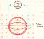
The induced current can also be generated when a coil of the constant area is rotated in a constant magnetic field. Here, also, the magnetic flux through the coil changes shown in the above figure. This is the basic principle used in electric generators.
A very interesting method to induce a current in a coil involves producing a change of magnetic flux in a nearby coil.

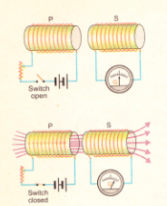
Two coils are placed side by side. The coil P is connected in series with a battery, a rheostat, and a switch, while the other coil S is connected to a galvanometer only. Since there is no battery in the coil S, one might expect that the current through it will always be zero.
Now, if the switch of the coil P is suddenly closed, a momentary current is induced in coil S. This is indicated by the galvanometer, which suddenly deflects and then returns to zero. No induced current exits in coil S as long as the current flows steadily in the coil P. An oppositely directed current is induced in coil S at the instant the switch of the coil P is opened. Actually, the current in P grows from zero to its maximum value just after the switch is closed. The current comes down to zero when the switch is opened.
Due to a change in current, the magnetic flux associated with the coil P changes momentarily. This changing flux is also linked with the coil S which causes the induced current in it. The current in coil P can also be changed with the help of rheostat.
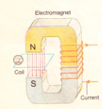
It is also possible to link the changing magnetic flux with a coil by using an electromagnetic instead of a permanent magnet. The coil is placed in the magnetic field of an electromagnetic.

Both the coil and the electromagnet are stationary. The magnetic flux through the coil is changed by changing the current of the electromagnet, thus producing the induced current in the coil.
