Joules law of heating equation
State Joule’s law of heating
“The heat produced in a conductor is:
(1) Directly proportion the square of current passing through the conductor,(H ∝ I²) keeping R and t constant;
(2) Directly proportion to the resistance of the conductor (H ∝ R) keeping I and t constant; and
(3)Directly proportional to the time of flow of current (H ∝ t) keeping I and R constant.”
joules law of heating formula
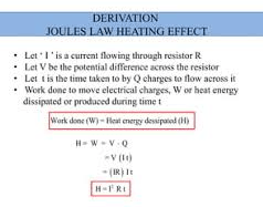
H=I²Rt
Verification of Joule’s law:
The above laws of heating by the electric current can be verified in the laboratory using a joule’s calorimeter.
To verify the above laws, heat is generated in a resist; coil R which is enclosed in a copper calorimeter containing water to about two-thirds of its volume. The ends of R are connected to finding terminals fixed to the lid. The calorimeter is enclosed in a wooden box to minimize the logs of heat. A is the ammeter to measure the current and V is the voltmeter to measure the potential difference across R. A rheostat is connected in the circuit to alter the current.
(a): Let W be the total water equivalent of the calorimeter (including the calorimeter, stirrer, and water ) and T1 the initial temperature. A current of I1 amperes is passed for a known interval of time (about 15 to 20 minutes) and the final temperature T2 (after correcting for the loss of heat by radiation ) is noted. Then, the quantity of heat produced =HI=W[θ1 -θ2]. Similarly, the experiment is repeated with different values of current I2,I3, etc.( after cooling the calorimeter to the initial temperature) and the corresponding quantities of heat produced H2, H3, etc are noted, keeping R and t constant.
Joules law derivation
Applications of heating effect of current
1:Safety fuse: A safety fuse is a short piece of wire with a low melting point. This is made of an alloy of tin and lead. The fuse wire is connected in series with the electrical installation and, when the current in the circuit exceeds the rated value, the fuse wire gets heated to a temperature higher than its melting point. The wire melts and the electric circuit is cut off. The temperature to which the wire gets heated is directly proportional to the cube of the radius. Thus the temperature depends only on the current flowing through the wire and its radius irrespective of its length.
2:Electric heater or stove, electric Radiators, and electric Iron. All these are based on the same principle that is produced when electric current flows through a wire. These contain coils of nichrome (an alloy of nickel and chromium) and large currents of the order of 3 to 5 amperes can be passed through them. In the case of an electric heater working 220 volts and consuming a power of 1000 watts, the current through the coils will be 4.55 amperes. The resistance of the coil will be 48.4 ohms. In the case of electric radiators, the coil is placed along the axis of a parabolic metallic reflector or at the focus of a concave reflector.
Seebeck effect
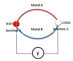
If two metal wires or strips A and B made of dissimilar metals are joined at the ends to form two junctions shown in the figure, then such a device is called a thermocouple.
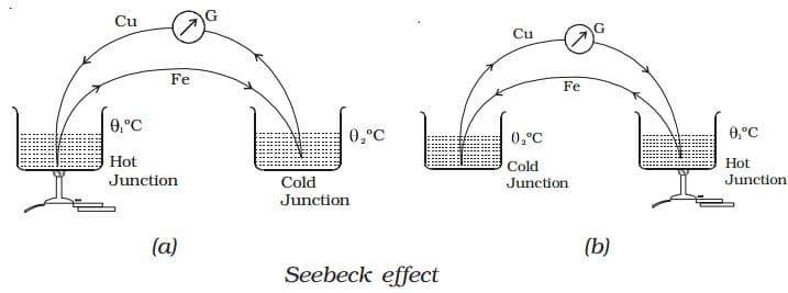
If two junctions of a thermocouple are kept at different temperatures, an electric current will be induced in the loop. This effect is called the Seebeck effect, and emf so developed is known as Seebeck emf or Thermo emf. The magnitude and direction of the emf depend upon the metals used and the temperature difference between hot and cold junctions. The Thermo emf induced is given by:
E = αμ + βθ²/2
Where θ is the temperature difference between hot and cold junctions.
Note that curve is parabolic. Note that natural temperature Remains unchanged when temperature of cold junction is curved.
At neutral temperature emf is maximum.
Peltier effect
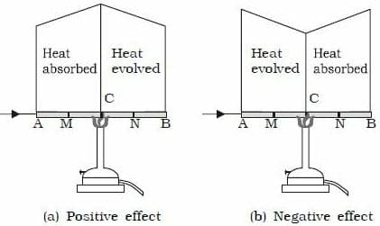
The converse of Seebeck effect is Peltier effect. If current is passed through a thermocouple or an external battery is applied across the two junctions of a thermocouple then one of the junctions becomes hot and other gets cold. The heat liberated or absorbed at one of the junctions is given by:
ΔH/ΔQ=πAB ,Which is Peltier emf.Where ΔQ is charge transferred.
Peltier coefficient is the amount of heat liberated per second when 1-A of current is passed through a thermocouple.
Thomson effect

If two sections of a conductor are at different temperatures then emf is developed between these two sections. This effect is known as “Thomson effect”.
Applications of thermal effects of current
- Electro power generation
- Refrigeration
- Detection and heat radiation
- Measurement of temperature
