Different Types of transformer and their uses

A transformer is an electrical device that is used to change a given alternating emf into a larger or smaller alternating emf. There are basically two main types of transformers step-up transformer which converts a low input voltage into high output voltage and step-down transformer which converts high input voltage to low voltage. Transformers are used for regulating AC current, rectification, battery charging, etc.
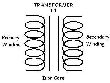 In the transformer, one coil is called the primary winding, and the other is called the secondary winding, and the load is connected to the secondary winding. The primary winding is the input winding, and the secondary winding is the output winding. It is common to refer to the side of the circuit that has the source voltage as the primary, and the side that has the induced voltage as the secondary.
The winding of the transformer is formed around the core. The core provides both a physical structure for placement of the windings and a magnetic path so that the magnetic flux is concentrated close to the coils. There are three general categories of core material: air, ferrite, and iron. The schematic symbol for each type is shown in the figure below: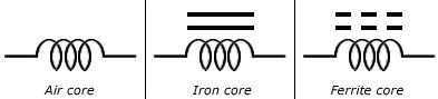
Air core and ferrite core transformers generally are used for high-frequency applications and consist of windings on an insulating shell that is hollow (air) or constructed of ferrite.
Iron core transformers generally are used for audio frequency (AF) and power applications. These transformers consist of windings on a core constructed from laminated sheets of ferromagnetic material insulated from each other.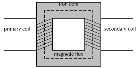
This construction provides an easy path for the magnetic flux and increases the amount of coupling between the windings.
In shell-type construction, both windings are on the same leg. Each type has certain advantages. Generally, the core type has more room for insulation and can handle higher voltages. The shell type can produce higher magnetic fluxes in the core, resulting in the need for fewer turns.
How does transformer works in physics?
It works on the principle of mutual induction between two coils. In principle, the transformer consists of two coils of copper, electrically insulated from each other, wound on the same iron core. The coil to which A.C power is supplied is called primary and that from which power is delivered to the circuit is called the secondary.
It should be noted that there is no electrical connection between the two coils but there are magnetically linked. Suppose that an alternating emf is applied to the primary. If some instant t the flux in the primary is changing at the rate of ΔΦ/Δt then there will be back emf included in the primary which will oppose the applied voltage. The instantaneous value of the self-induced emf is given by:
![]()
If the resistance of the coil is negligible then the back emf equal and opposite to applied voltage Vp.
![]()
Where Np is the number of turns in the primary.
Assuming the flux through the primary also passes through the secondary, i.e, the two coils are tightly coupled, the rate of change of flux in the secondary will also be ΔΦ/Δt and the magnitude of the induced emf across the secondary is given by:
![]()
Where Ns is the number turns in the primary.
Dividing the above two relations we get:

It is important to note that the electrical power in a transformer is transformed from its primary to the secondary coil by means of changing flux for an ideal case the power in input to the primary is near equal to the power output from the secondary is:
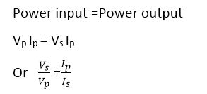
Ip is the current in the primary and Is in the secondary. The currents are thus inversely proportional to the respective voltage. Therefore, in a step-up transformer when the voltage across the secondary is raised, the value of current is reduced.
This is the principle behind its use in the electric supply network where the transformer increases the voltage and reduces the current so that it can be transmitted over long distances without much power loss. When current I passes through a resistance R economically than the power loss due to heating effect I 2 R.
Suppose R is the resistance of the transmission line. In order to minimize the loss during transmission, it is not possible to reduce R because it requires the use of thick copper wire which becomes highly uneconomical. The purpose is well served by reducing I.
At the generating power station, the voltage is stepped up to several thousand volts, and power is transmitted to long distances without much loss. Step down transformers then decreases the voltage to a safe value at the end of the line where the consumer of electric power is located. Inside a house, a transformer may be used to step down the voltage from 250 volts to 9 volts for ringing bell or operating a transistor radio. Transformers with several secondaries are used in television and radio receivers where several different voltages are required.
Only in an ideal transformer, the output power is nearly equal to the input power. But in an actual transformer, this is not the case. The output is always less than input due to power losses. There are two main causes of power loss, namely-eddy currents, and magnetic hysteresis.
In order to enhance the magnetic flux, the primary and secondary coils of the transformer are wound on a soft iron core. The flux generated by the coils also passes through the core. As magnetic flux changes through a solid conductor, induct currents are set up in closed paths in the body of the conductor. These induced currents are set up in the direction perpendicular to the flux and are known as eddy currents.
It results in power dissipation and heating of the core material. In order to minimize the power loss due to the flow of these currents, the core is laminated with insulation in between the layers of lamination’s which stops the flow of eddy currents. Hysteresis loss is the energy expended to magnetize and demagnetize the core material in each cycle of the A.C.
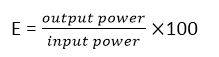
Due to these power losses, a transformer is far from being an ideal. Its output power is always less than its input power. The efficiency of a transformer is defined as:

In order to improve efficiency, care should be exercised to minimize all the power losses. For example, the core should be assembled from the laminated sheets of a material whose hysteresis loop area is very small. The insulation between lamination sheets should be perfect so as to stop the flow of eddy currents. The resistance of the primary and secondary coils should be kept to a minimum. As power transfer from the primary and secondary takes place through flux linkages, so the primary and secondary coils should be wound in such a way that flux coupling between them is maximum.
Types of transformer
Functionally, the transformers used in electronic circuits can be classified according to the frequency range over which they operate such as:
Audio frequency (AF) transformers
They are designed to operate over the audio frequency (AF) range of 20 Hz to 20 kHz, have a laminated core, and are usually smaller than power transformers. They are primarily used for impedance matching and, in some cases, for voltage amplification. Such transformers are usually designated according to their applications as input or output transformer, modulation transformer, and inter stage transformer etc. Usually, they are rated by their primary and secondary impedance and current-carrying capability.
Radio frequency (RF) transformers
They are designed to operate at high frequencies (above audio range) and are referred to either as an intermediate frequency (IF) transformers or radio frequency transformers. They may have air core or ferrite core. Most of the RF transformers have either one or both of the windings tuned in conjunction with the capacitor, they form a resonate circuit which works best at one particular frequency.
Power transformers
Usually, they have a laminated core and have one primary winding but several secondary windings insulated from each other. They are commonly used in the power supply of electronic equipment and provide various ac voltage necessary for the production of dc voltages.
Practical transformer
Up to this point, transformer operation has been discussed from an ideal point of view. That is, the winding resistance, the winding capacitance, and nonideal core characteristics were all neglected and the transformer was treated as if it had an efficiency of 100%. For studying the basic concepts and in many applications, the ideal model is valid. However, the practical transformer has several non-ideal characteristics of which you should be aware of.
Winding Resistance
Both the primary and the secondary windings of a practical transformer have winding resistance. You learned about the winding resistance of inductors. The winding resistance of a practical transformer are represented as resistors in series with the winding as shown in the figure:
Figure……………….
Winding resistance in practical transformer results in less voltage across a secondary load. Voltage drops due to the winding resistance effectively subtract from the primary and secondary voltages and result in load voltage that is less than that predicted by the relationship V sec =nV pri .In many cases, the effect is relatively small and can be neglected.
Losses in the Core
there is always some energy conversion is the core material of a practical transformer. This conversion is seen as heating of ferrite and iron cores, but it does not occur in air cores. Part of this energy conversion is because of the continuous reversal of the magnetic field due to the changing direction of the primary current; This component of the energy conversion is called hysteresis loss.
The rest of the energy conversion to heat is caused by eddy currents produced when voltage is induced in the core material by the changing material flux, according to Faraday’s law. the eddy currents occur in circular patterns in the core resistance, thus producing heat. this conversion to heat is greatly reduced by the use of laminated construction of iron cores. These thin layers of ferromagnetic material are insulated from each other to minimize the buildup of eddy current by confining them to a small area and to keep core losses to a minimum.
Magnetic Flux Leakage
in an ideal transformer, all of the magnetic flux produced by the primary current is assumed to pass through the core to the secondary winding, and vice versa. in a practical transformer, some of the magnetic flux lines break out of the core and pass through the surrounding air back to the other end of the winding. For the magnetic field produced by the primary current. Magnetic flux leakage results in a reduced secondary voltage.
Figure,……………………….
The percentage of magnetic flux that actually reaches the secondary winding determines the coefficient of the coupling of the transformer. For example, if nine out of the ten flux lines remain inside the core, the coefficient of coupling of 0.90 or 90%. Most iron core transformers have a very high coefficient of coupling (greater than 0.99), while ferrite-core and air-core devices have lower values.
Winding Capacitance
As you leaned, there is always some stray capacitance between adjacent turns of a winding. These stray capacitances result in an effective capacitance in parallel with each winding of a transformer.
The stray capacitances have very little effect on the transformer’s operation at low frequencies ( such as power line frequencies) because the reactance (X c) is very high. However, at higher frequencies, the reactance’s decrease and begin to produce a bypassing effect across the primary winding and across the secondary load. As a result, less of the total primary current is through the primary winding, and less of the total secondary current is through the load. This effect reduces the load voltage as the frequency goes up.
See More: Electricity and Magnetism
Transformer Power Rating:
A power transformer is typically rated in volt-amperes (VA), primary/secondary voltage, and operating frequency. For example, a given transformer rating may be specified as 2 kVA,500/50,60 Hz. The 2kVA value is the apparent power rating. The 500 and the 50 can be either secondary or primary voltages. the 60 Hz is the operating frequency.
The transformer rating can be helpful in secondary the proper transformer for a given application. let’s assume, for example, that 50 V is the secondary voltage, in this case, the load current is :
Formulas,…………………………….
Transformer Efficiency:
Recall that the power delivered to the load is equal to the power delivered to the primary in an ideal transformer because the non ideal characteristic just discussed result in power loss in the transformer, the secondary (output) power is always less than the primary (input) power. The efficiency( η) of a transformer is a measure of a percentage of the input power that is delivered to the output.
Most power transformers have efficiencies in excess of 95% under load.
See Also: Difference between step up and step down transformer
One Comment