Factors Affecting Resistance
 Resistance is the property of the material that restricts the flow of electrons. There are four factors affecting resistance which are Temperature, Length of wire, Area of the cross-section of the wire, and nature of the material.
When there is current in a conductive material, the free electrons move through the material and occasionally collide with atoms. These collisions cause the electrons to lose some of their energy, and thus their movement is restricted. This restriction varies and is determined by the type of material. The property of a material that restricts the flow of electrons is called resistance.
When there is current through any material that has resistance, heat is produced by the collisions of free electrons and atoms. Therefore, wire, which typically has a very small resistance, becomes warm when there is sufficient current through it.
See Also: Types of electric charge
What is the unit of resistance?
Resistance, R, is expressed in ohms and is symbolized by the Greek letter omega (Ω).
“One ohm (1Ω) of resistance exists if there is one ampere (1A) of current in a material when one volt (1V) is applied across the material.”
What is conductance?
The reciprocal of resistance is conductance, symbolized by G. It is a measure of the ease with which current is established. The formula is:
G=1/R
The unit of conductance is the Siemens, abbreviated S. For example, the conductance of a 22KΩ resister is G=1/22KΩ=45.5µs. Occasionally, the obsolete unit of mho is still used for conductance.
See Also: Coulomb’s law
List of Factors affecting resistance
Resistance decreases with an increase in temperature. The thermistor is a temperature-dependent resistor and its resistance decreases as temperature rises. The thermistor is used in a circuit that senses temperature change. There are four factors on which resistance depends.
- Length(L)
- it’s cross-sectional area(A)
- the type of material
- nature of material
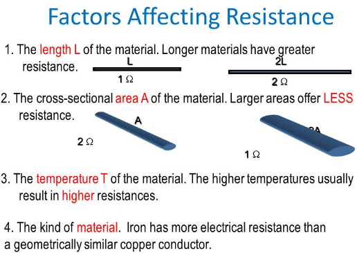
The resistance of a wire depends both on the cross-sectional area and length of the wire and on the nature of the material of the wire. Thick wires have less resistance than thin wires. Longer wires have more resistance than short wires. Copper wire has less resistance than thin steel wire of the same size. Electrical resistance also depends on temperature. At a certain temperature and for a particular substance.
How does the length of the wire affect resistance?
The resistance R of the wire is directly proportional to the length of the wire :
R α L …..(1)
It means, if we double the length of the wire, its resistance will also be doubled, and if its length is halved, its resistance would become one-half.
Relation of resistance with area:
The resistance R of a wire is inversely proportional to the area of cross-section A of the wire as:
R α 1/A ……(2)
It means that a thick wire would have smaller resistance than a thin wire. After combining the equations (1) and (2) we get;
R α L/A
R=ρL/A ….(3)
Where ρ is the constant of proportionality, known as specific resistance. Its value depends upon the nature of the conductor i.e copper, iron, tin, and silver would each have different values of ρ. From equation (3) we have;
ρ=R A /L ….(4)
If L=1m, A=1m² then ρ=R.Thus equation (4) gives the definition.
See also: Difference between Voltage and current
What is specific resistance?
The resistance of a one-meter cube of a substance is equal to its specific resistance. The unit of ρ is ohm-meter (Ωm). Below given a table of some metals with specific resistance:
Metal specific resistance(10-8Ω)
- Silver 1.7
- Copper 1.69
- Aluminum 2.75
- Tungsten 5.25
- Platinum 10.6
- Iron 9.8
- Ni-chrome 100
- Graphite 3500
What are conductors?
A material or an object that conducts heat, electricity, light, or sound is called a conductor. Metal wires are good conductors of electricity and offer less resistance to the flow of current. Why do metals conduct electricity?… Metals like silver and copper have an excess of free electrons which are not held strongly with any particular atom of metals. These free electrons move randomly in all directions inside metals. When we apply an external field these electrons can easily move in a specific direction.
This movement of free electrons in a particular direction under the influence of an external field causes the flow of current in metal wires.
How does resistance increase with temperature?
The conductors have a low value of resistance. The resistance of conductors increases with an increase in temperature. This is due to an increase in the number of collisions of electrons with themselves and with the atoms of the metals. Gold, silver, copper, aluminum, and other metals are good examples of conductors. Earth is also a very good and big conductor.
What are insulators?
A material that does not easily transmit energy, such as electric current or heat is called an insulator. why insulators do not conduct electricity?. All materials contain electrons. The electrons in insulators, like rubber, however, are not free to move. They are tightly bound inside atoms. Hence, current cannot flow through an insulator because they are no free electrons for the flow of current. Insulators have a very large value of resistance. Glass, wood, plastic, fur, silk, etc.
Combinations of resistance in the electric circuit
There are two possible combinations of resistance in electric circuits:
-
Series combination
-
Parallel combination
-
Series combination:
In series combinations, resistors are connected end to end and electric current has a single path through the circuit. This means that the current passing through each resistor is the same.
The current is the same through all points in the series circuit. The current through each resistor in a series circuit is the same as the current through all the resistors that are in series with it. In the above figure, three resistors are connected in series to a DC voltage source.
At any point in this circuit, the current into that point must equal the current out of that point. Notice also that the current out of each resistor must equal the current into each resistor because there is no place where part of the current can branch off and go somewhere else.
Therefore, the current in each section of the circuit is the same as the current in all other sections. It has only one path going from the positive(+) side of the source to the negative (_) side.
Total series resistance:
The total series resistance of a series circuit is equal to the sum of the resistance of each individual series resistor. When resistors are connected in series, the resistor values add because each resistor offers opposition to the current in direct proportion to its resistance. A greater number of resistors connected in series creates more opposition to the current. More opposition to the current implies a higher value of resistance. Thus, every time a resistor is added in series, the total resistance increases.
See also: Types of electric charge
Formula of total resistance in series combination:
For any number of individual resistors connected in series, the total resistance is the sum of each of the individual values.
Rt=R1+R2+R3+R4+………..+Rn
Where Rt is the total resistance and Rn is the last resistor in the series string. For example, if there are 3 resistors in a series . the total resistance formula will be
Rt=R1+R2+R3
If there are six resistors in series (n=6), the total resistance formula will be:
Rt=R1+R2+R3+R4+R5+R6
2:Parallel combination:
When two or more resistors are individually connected between the same two separate points, they are in parallel with each other. A parallel circuit provides more than one path for current.
Each current path is called a branch. A parallel circuit is one more that has more than one branch. Three resistors are connected in parallel shown in the above figure. When resistors are connected in parallel, the current has more than one path. The number of current paths is equal to the number of parallel branches.
The formula for total parallel resistance:
Since Vs is the voltage across each of the parallel resistors in the above figure, by Ohm’s law I=Vs/R:
Vs/Rt= Vs/R1+ Vs/R2+ Vs/R3…….(1)
The term Vs can be factored out of the right side of the equation and canceled with Vs on the left side, leaving only the resistance terms.
1/Rt = 1/R1 + 1/R2 + 1/R3 ……(2)
Recall that the reciprocal of resistance (1/R) is called conductance, which is symbolized by G. The unit of conductance is the Siemens (s). Equation (2) can be expressed in terms of conductance as:
Gt = G1 + G2 + G2
Solve for Rt in equation (2) by taking the reciprocal of that is inverting both sides of the equation.
Rt= 1/ (1/R1) + (1/R2)+ (1/R3)
Related topics:
- Difference between current and voltage
- Ohm’s law formula
- Types of charges
- Coulomb’s law formula
- Gauss’s law
- Difference between conductors and insulators
- Lenz’s law
Handpicked links
This information is very reliable