Types of Diffraction of light with examples
In this post, You’ll Learn about Diffraction of light in a comprehensive way.
So, If you want to get benefits from this post, then you’ll love this post.
Contents:
- Diffraction Definition
- Diffraction Types
- Diffraction Examples
- Much more
Let’s dive right in:
What is Diffraction of light?
The bending of light waves around the corners of an obstacle and spreading of light waves into geometrical shadow is called diffraction. Fraunhofer Diffraction and Fresnel Diffraction are two Types of Diffraction of Light. Bending of Light around the corners of Window is an example of Diffraction.
Diffraction effect depends upon the size of the obstacle. Diffraction of light takes place if the size of the obstacle is comparable to the wavelength of light. Light waves are very small in wavelength,i.e, from 4×10⁻⁷ m to 7 × 10 -7 m. If the size of opening or obstacle is near to this limit, only then we can observe the phenomenon of diffraction.
Types of diffraction in physics
Diffraction of light can be divided into two types:
- Fraunhofer Diffraction
- Fresnel Diffraction
Fraunhofer Diffraction
In Fraunhofer diffraction:
- Source and the screen are far away from each other.
- Incident wavefronts on the diffracting obstacle are plane.
- Diffraction obstacle gives rise to wavefronts which are also plane.
- Plane diffracting wavefronts are converged by means of a convex lens to produce a diffraction pattern.
Fresnel Diffraction
In Fresnel diffraction:
- Source and screen are not far away from each other.
- Incident wavefronts are spherical.
- Wavefronts leaving the obstacles are also spherical.
- The convex lens is not needed to converge the spherical wavefronts.
See Also: Refraction of light
Diffraction of light
In Young’s double-slit experiment for the interference of light, the central region of the fringe system is bright. If light travels in a straight path, the central region should appear dark i.e., the shadow of the screen between the two slits. Another simple experiment can be performed by exhibiting the same effect.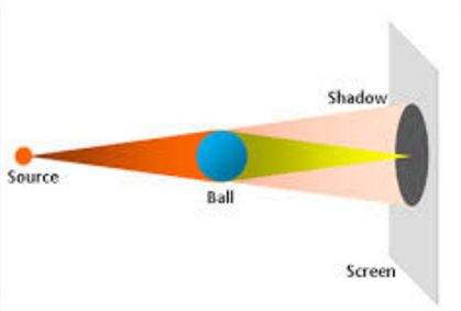
Consider that a small and smooth ball of about 3 mm in diameter is illuminated by a point source of light. The shadow of the object is received on a screen as shown in the figure. The shadow of the spherical object is not completely dark but has a bright spot at its centre. According to Huygens’s principle, each point on the rim of the sphere behaves as a source of secondary wavelets which illuminate the central region of the shadow.
These two experiments clearly show that when light travels past an obstacle, it does not proceed exactly along a straight path, but bends around the obstacle. The phenomenon is found to be prominent when the wavelength of light is compared with the size of the obstacle or aperture of the slit. The diffraction of light occurs, in effect, due to the interference between rays coming from different parts of the same wavefront.
See Also : Interference of light
Diffraction due to Narrow slit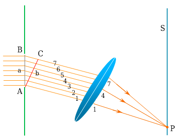
The figure shows the experimental arrangement for studying diffraction of light due to the narrow slit. The slit AB of width d is illuminated by a parallel beam of monochromatic light of wavelength λ. The screen S is placed parallel to the slit for observing the effects of the diffraction of light. A small portion of the incident wavefront passes through the narrow slit. Each point of this section of the wavefront sends out secondary wavelets to the screen. These wavelets then interfere to produce the diffraction pattern. It becomes simple to deal with rays instead of wavefronts as shown in the figure.
In this figure, only nine rays have been drawn whereas actually there are a large number of them. Let us consider rays 1 and 5 which are in phase on in the wavefront AB. When these reach the wavefront AC, ray 5 would have a path difference ab say equal to λ/2. Thus, when these two rays reach point p on the screen; they will interfere destructively. Similarly, each pair 2 and 6,3 and 7,4 and 8 differ in the path by λ/2 and will do the same. But the path difference ab=d/2 sinθ.
The equation for the first minimum is, then
d/2 sinθ =λ/2
or d sinθ=λ
In general, the conditions for different orders of minima on either side of the centre are given by:
d sinθ =mλ
where m=± (1,2,3,….)
The region between any two consecutive minima both above and below O will be bright. A narrow slit, therefore, produces a series of bright and dark regions with the first bright region at the centre of the pattern.
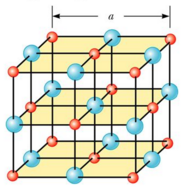
Diffraction of X-rays by Crystals
The wavelength of an electromagnetic wave can be determined if a grating of the proper spacing i.e. of the order of wavelength λ of the wave, is available. X-rays are electromagnetic waves of very short wavelengths ( of the order of 0.1 nm). It would be impossible to construct a grating having such a small spacing by the cutting process. However: the atomic spacing in a solid is known to be about 0.1 nm. In 1913, Max von Laue suggested that the regular array of atoms in a crystal solid could act as a three-dimensional diffraction pattern are complex because of the three-dimensional diffraction grating for X-rays. The subsequent experiment confirmed this prediction. The diffraction patterns are complex because of the three-dimensional nature of the crystal. Nevertheless, x-ray diffraction has proved to be an invaluable technique for studying crystalline structures and for understanding the structure of matter.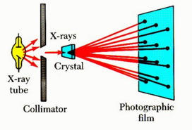
A collimated beam of x-rays is incident on a crystal. The diffracted beams are very intense in certain directions, corresponding to constructive interference from waves reflected from layers of atoms in the crystal. The diffracted beams can be detected by a photographic film, and they form array of spots known as a Laue pattern. One can deduce the crystalline structure by analyzing the positions and intensities of the various spots in the pattern.
Bragg’s Equation
Suppose that an x-ray beam is incident at an angle θ on one of the planes. The beam can be reflected from both the upper plane and the lower plane travels farther than the beam reflected from the upper plane. It is clear that beam 2 travels a greater distance than beam 1 after reflection from atoms of the plane. Thus the distance BC+CD is the effective path difference between the two reflected beams 1 and 2.
Watch also:
Related Searches of Diffraction of Light:
- Reflection of light
- Properties of Light
- Refraction of light
- Interference
- Diffraction grating
- Difference between interference and diffraction of light
Related Searches In Physics are:
External sources
- https://en.wikipedia.org/wiki/Diffraction
- https://www.quora.com/What-is-diffraction-of-light